Anchor Build Guide
Hardware Version: Pilot run
Build time: about 45 minutes per anchor.
A complete robot consists of fours anchors, a gantry, and a gripper. First you should have printed the parts according to the print guide
Tool list
- Mini screwdriver with a bit set
- Soldering station
- Cross locking tweezers Mandatory you'll jump off a bridge without them.
- Mini side cutters
- Super glue (loctite super glue “professional liquid” recommended)
Note
The color of the printed parts in this guide varies from image to image because some photos have been re-taken to keep the guide up to date with revisions
Print the long hexagonal screwdriver bit holder. You will need a brim when printing it. Most precision screwdrivers come with a set of bits with 4mm hex shanks. This is designed to fit those but be long enough to be held in a drill from the outside of this frame.

Glue the two sides of the spool together with the grooved wheel on the outside. Use small dabs of superglue around the ‘shelf’ on the spool where the solvent would be able to evaporate more easily.


Once the glue is dry enough to handle, press a 4x14mm steel tube into one of the 4x13x5 bearings so one end is flush. Place two M4 washers onto the tube and press this into the hole on the grooved wheel side of the spool.


Cut away the sacreficial bridge from this U-shaped region in the frame.

Noise Dampening
Insert four rubber noise dampeners into the four motor screw holes as show, so that the thicker end is pointed outwards.

Cut out a square piece of adhesive foam grip tape and an 8mm wide strip of tape and stick them in the pictured locations. These serve to prevent the motor from making rigid contact with the frame. If it makes rigid contact the robot gets loud because the frame and wall act like a speaker.

Spool installation
Press a bearing into the pictured hole in the narrow rib. Make it flush with both sides.

Insert all four M3x10 motors screws in their holes. It’s a bit harder to insert them later, but still possible.

Insert an M4x12 screw into the bearing that is pressed into the frame. Place two M4 washers onto it on the inside of the rib. Now you have to get through the fiddly step of installing the spool without these two washers falling off. they are important. without that spacing, the spool can touch the frame, and that makes noise. you will need to pull the screw back as pictured.


Place the belt onto the spoo, then slide the spool into place on the frame. The spool’s grooves side faces the thick rib. Slide the bearing down the slot, while pressing the M4x12 screw on the other side in so the washers don't fall off. when the bearing is fully seated and the spool is straight, the M4 screw will fit into the hole on the flat side of the spool. Screw it in using the printed screwdriver and an appropriately size hex driver.


That was the hardest step, it’s downhill from here.
Press the bearing retainer into the void that remains in the tick rib, and secure it with the flat head M3x6 screw.

Motor installation
Extra motor setup if you did not buy the hardware kit
If you purchased your motors elsewhere you may need to perform some additional steps.
- Install the short 4-wire jumper of the MKS_SERVO42C between the board and stepper. There is only one way it will fit.
- Connect the motor to 24v power
- Perform motor self calibration with a bare shaft
- Set the mode to UART
- Set the uart baud to 38400
If you bought the hardware kit from us, those steps were performed before the motor was packed, though it can't hurt to confirm the settings.
When handling the motor be careful not to ever place it on the PCB. the three buttons can break off.
Install a 20 tooth aluminum pully wheel on the shaft. tighten both set screws. Make it flush with the end of the shaft for now.

Work the belt over the pully wheel with a tool and install the motor with the larger connector facing downwards. (down is the narrower end of the frame.) Tighten the screws by using the printed screwdriver and the holes in the frame and spool to access the screws.


There is a cutaway on the top face from which you can more easily access the pully wheel set screw with an allen wrench. Loosen the set screws on the aluminum wheel and adjust it's depth until the wheel runs as quietly as possible. Retighten.

Spin your spool slowly and confirm it makes a full rotation without excessive friction. If you feel bumps only when moving fast, ignore that, it’s an electrical effect.

For power anchors only
One of the anchors in your robot needs to supply power to the gripper. It doesn’t matter which one, but you need to install slip ring at this point before too many other things get in the way.
Power is supplied to the gripper via a wire that takes the place of the fishing line, and is transferred via a slip ring at each end.
Take a slip ring and identify the wires that come out of the rotor. Insert these two wires into the metal tube that leads into the center of the spool.

Wiggle and push the wires until they come out of the outlet in the spool’s center. Pull them the rest of the way through. Seat the slip ring in its place and secure it with three M3x4 screws.
Leave the wires that come out of the spool center hanging for now.


Raspberry Pi installation
Use the raspberry pi sd card imager tool to create a card that is pre configured with your wifi password, ssh turned on, and a username you can login with. See Raspberry Pi Setup for more detail. You can also do this later.
Setting “pi” as the username and password is standard practice for people who know that real security is only possible if you throw all the electronics in the lake
Insert the SD card into the Raspberry Pi Zero 2 W. Install an aluminum heatsink on the SOC.
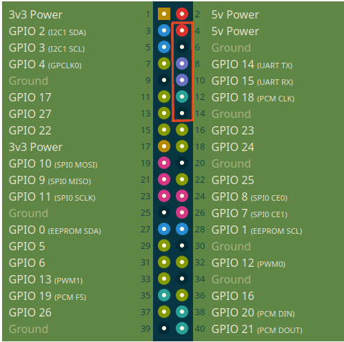
Solder a 6 pin straight header on the pins shown in the image, protruding from the back.

Note
The 6-pin header's long end should come out of the back of the Raspberry Pi Zero 2W
Locate one 80mm mini raspi camera cable.
Open the Raspberry Pi camera Module 3. Take care to ground yourself before handling the camera. Discard any other ribbons that shipped with the camera.
Connect the mini ribbon's wide end to the camera. The black painted side of the ribbon goes towards the back side of the PCB and the gold plated side goes towards the camera lens.
Connect the mini ribbon's narrow end to the raspberry pi. the black side goes towards the top of the PCB
To attach a ribbon cable, gently pull out both sides of the plastic retaining clip, insert the ribbon end, and push the retainer back into place.
Be careful with the raspberry pi’s ribbon cable retention clip, it is extremely delicate.


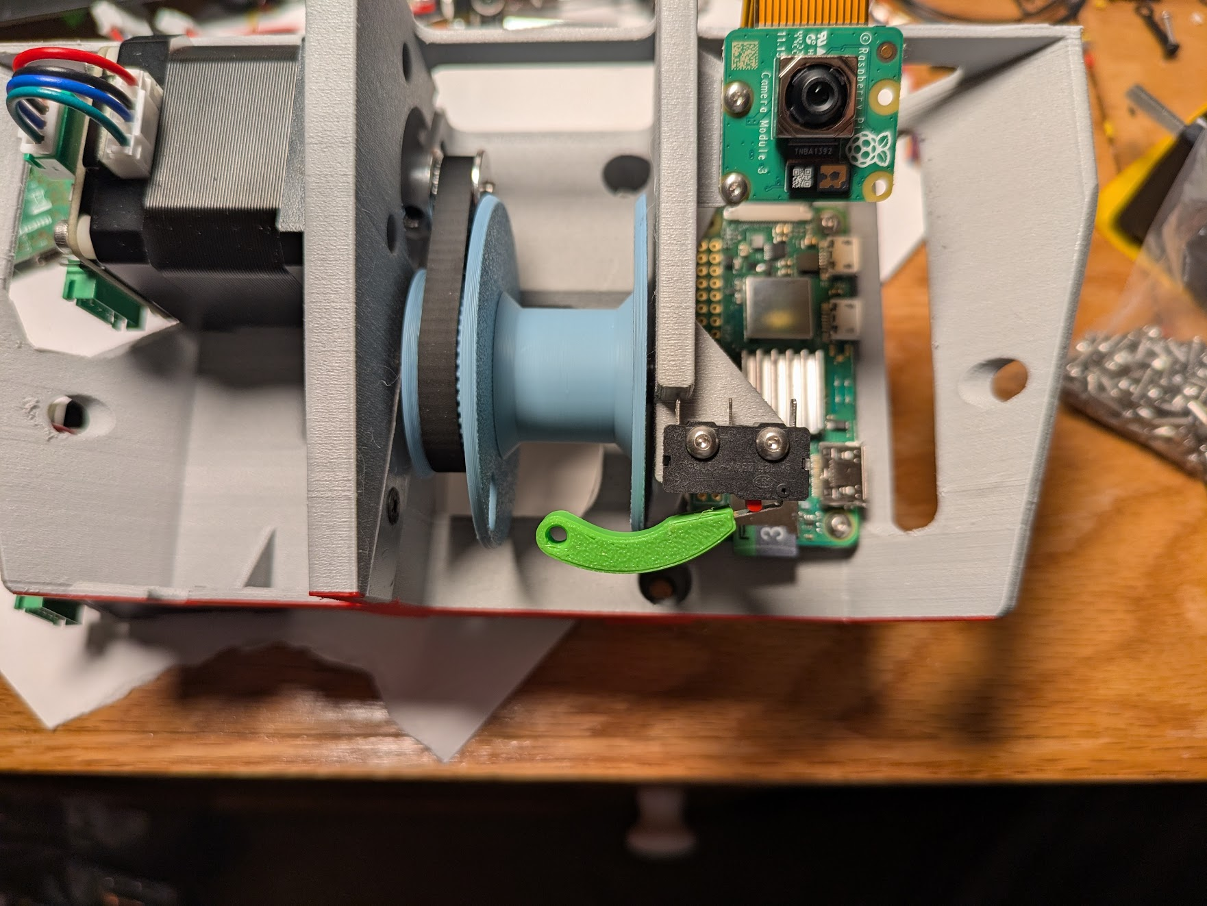
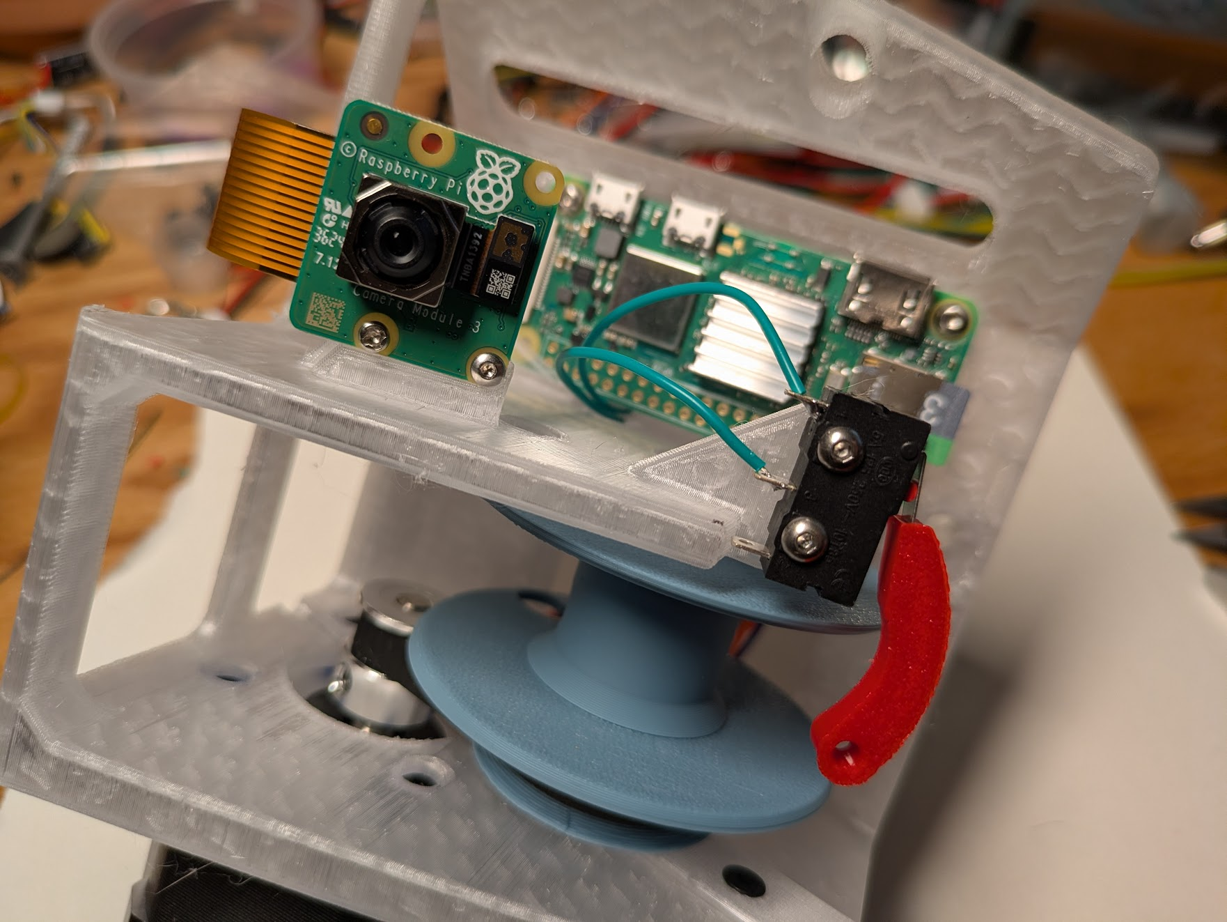
Place the raspberry pi in the frame as shown. First, make the pin header go through the oval, then slide the upper corner under the slot, then press the lower corner onto the peg. Secure with two m2.5 x 6 screws. Attach the camera with two M2x4 screws


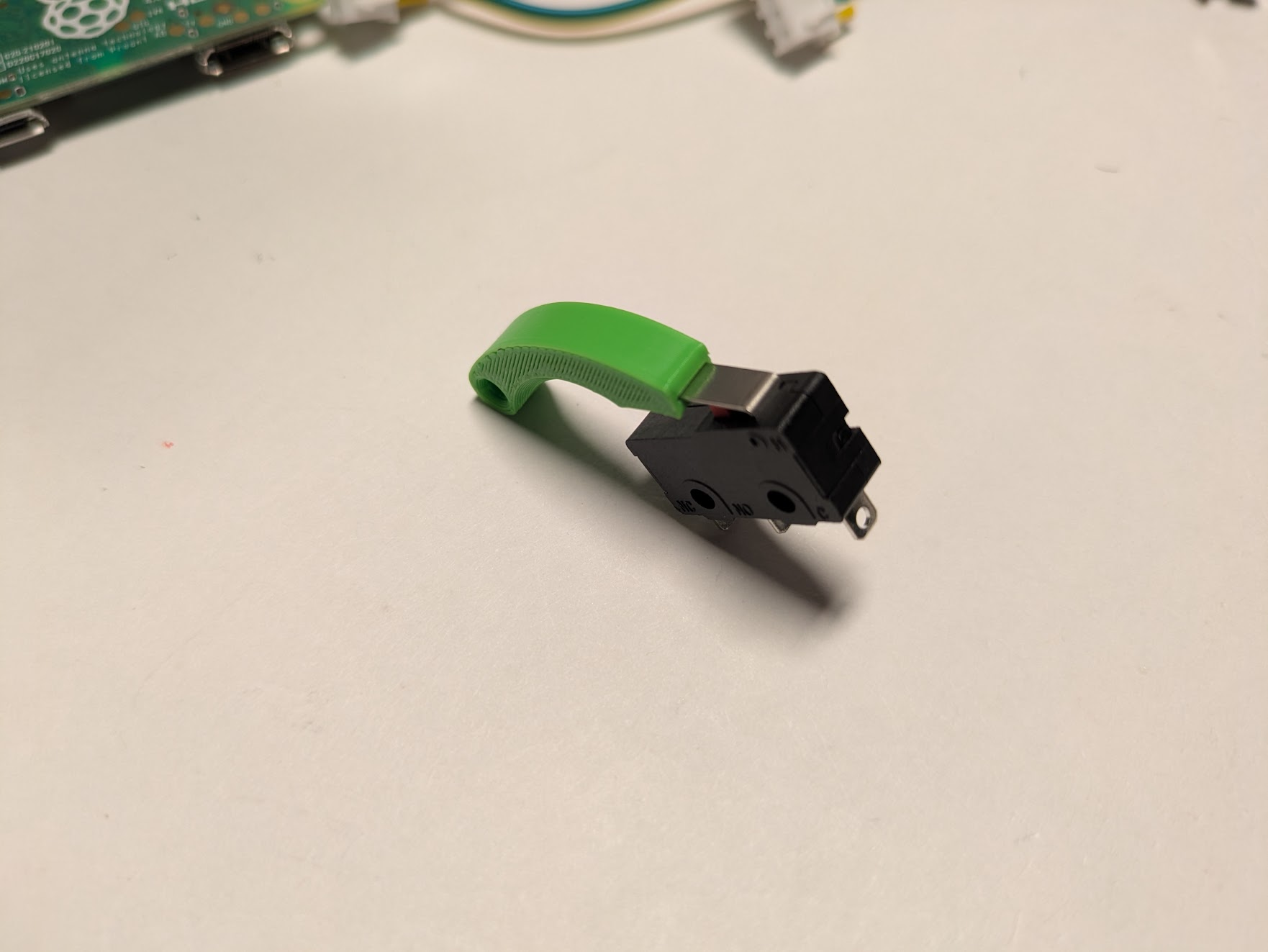
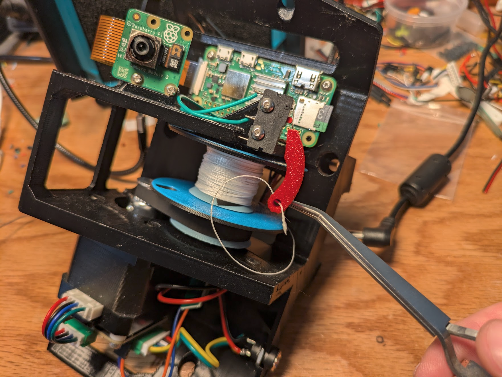
Insert the steel lever arm of a microswitch into the slot of a printed line position sensing lever. Do this while the lever is depressed and hold firmly to avoid bending the metal while pressing it in till it bottoms out. Install the switch onto the frame in the position indicated in the image. It should curve upwards and the hole should be centered above the spool. Secure with two M2.5x10 screws.
Power supply circuit
Screw a nut onto the DC barrel Jack. (it should come pre-installed, but may fall off in shipping. It’s important this is done before the wiring.

Locate the long cable that came with the MKS_SERVO42C. It has two different ends that are mirrors of each other. You can use either end to make a cable that matches this photo, VIN and GND will be red and black on one end, or yellow and green on the other end. Note the orientation of the white connector in the photo. Cut the power and ground wires to 7 cm, and all others to basically zero. Solder the black and red leads (or green and yellow) to the barrel jack. (it’s long leg is ground) The motor will receive 24v from this connector.

Get one small DC step down converter from your kit (the green one).
Cut two 2.5cm pieces of 28 guage wire or similar and solder them to GND and IN+.
Solder the step down regulator’s inputs to the 24v of the jack.


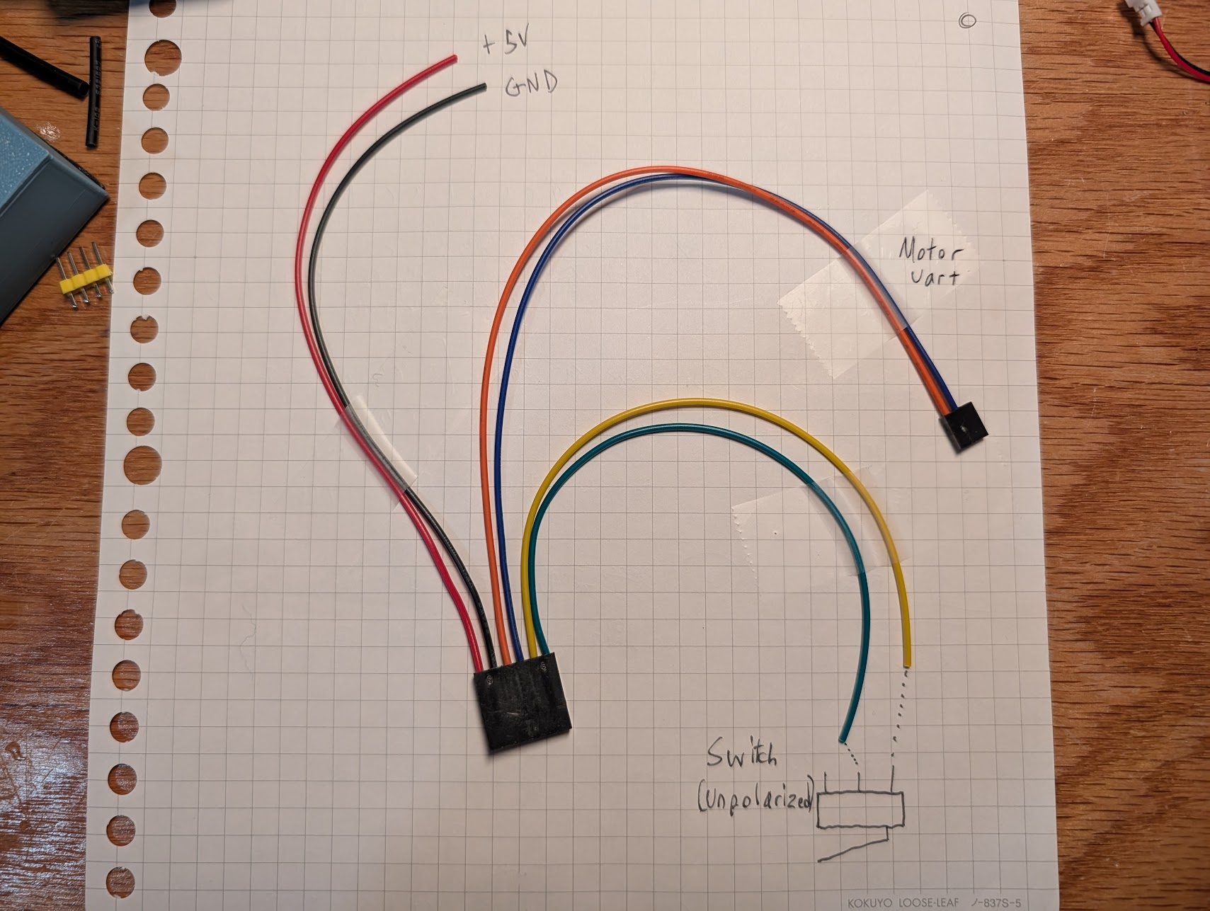
Find one of the pre-made anchor connectors. Find the two red and the black wires coming from the 6-pin connector. Solder these to the output of the DC step down converter. The converter has only on ground terminal to be used for both input and output, so you may have to solder one of the ground wires by just sticking it to the side of the other. You can find a diagram of this wire in the wire guide.
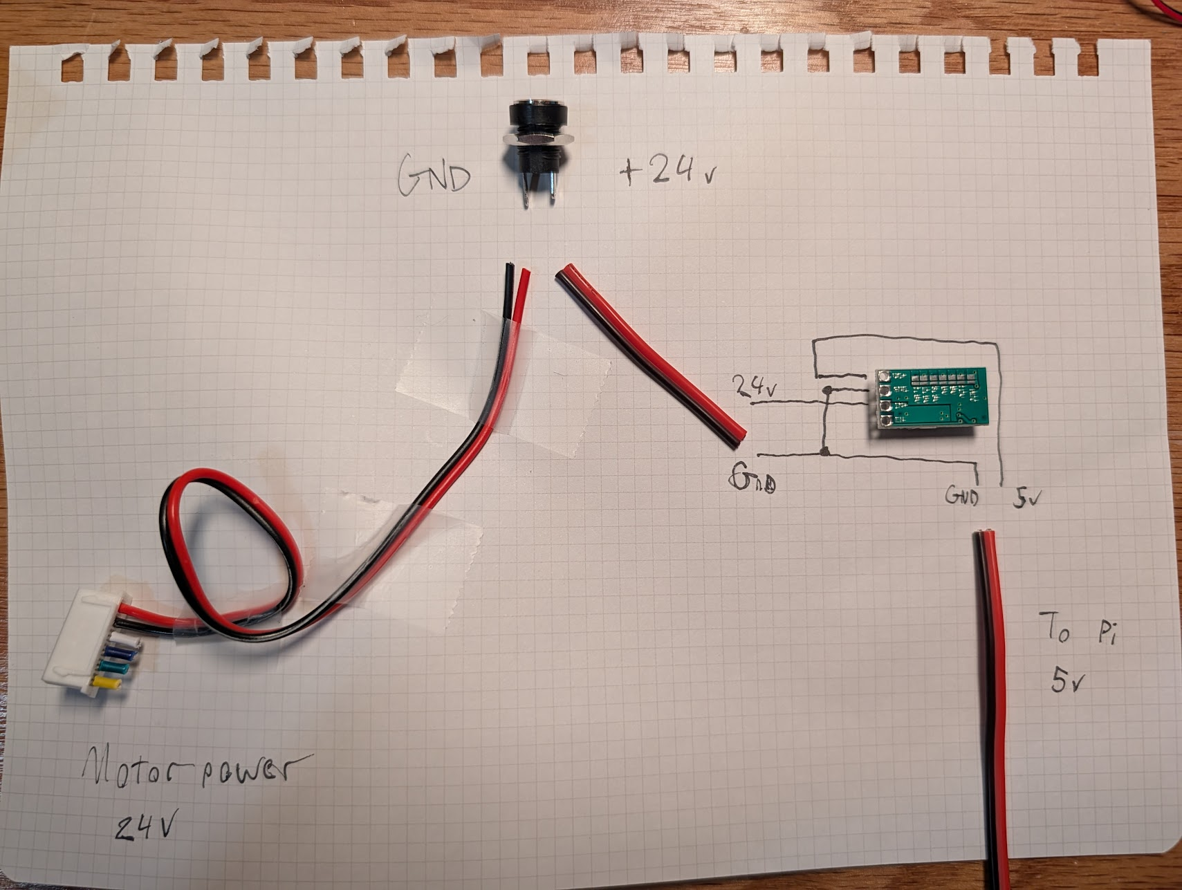

Plug the white connector into the large port on the motor board. Push the barrel jack into the U shaped recess and tighten the nut. the smaller black connector is the UART communication line. plug this into the protruding pins on the motor board right between the large plug and the screw. Refer to the image, blue should be TX and orange should be RX on the motor board.


Feed the black 6-pin connector through the holes in the back of the frame and plug it into the header on the raspberry pi, with V+ at the bottom (closest to the SD card end)

Feed the final two loose wires from the back to the front through the hole between the narrow rib and the raspberry pi. Cut them to an appropriate length, strip, and solder them to the right two contacts of the micrswitch. polarity is irrelevant.

Power Anchor Steps
If this is the power anchor, (the one with a slip ring installed) connect the input side of the slip ring to 24v power at the barrel jack. Be sure to use a stripper suitable for such a small guage of wire

Winding the Spool
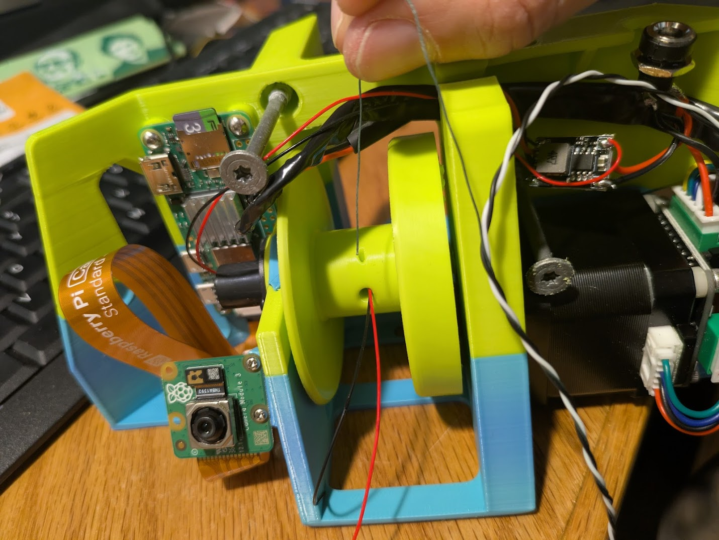
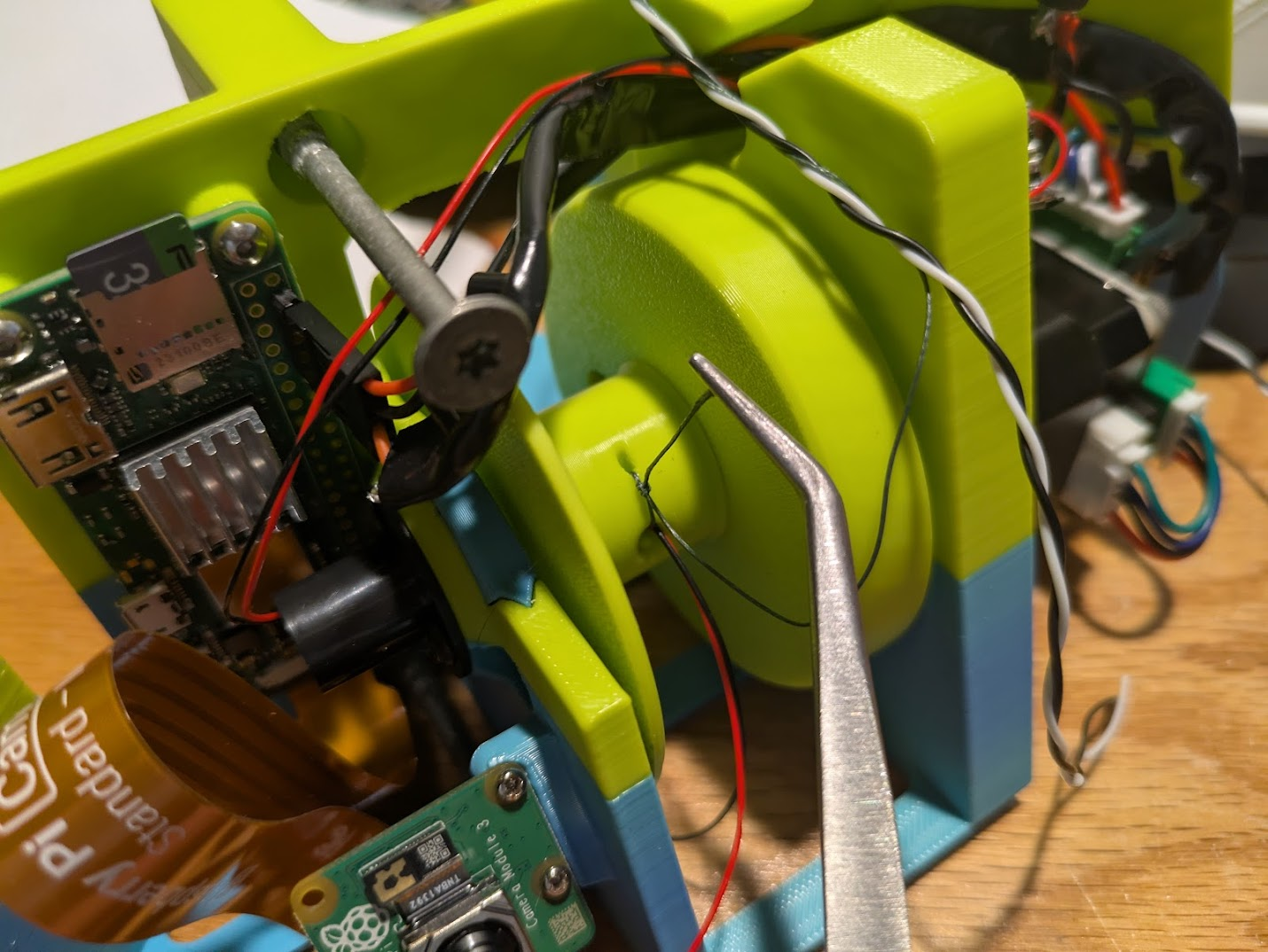
Thread either fishing line alone or the end of a 7 meter segment of power line (for power anchors only) into the small hole on the spool such that it comes back out of the adjacent larger hole and tie it off.
Trim back the black and white wires of the powerline so that they end where the wires of the slip ring end, with just a little slack. The Fishing line must take any tension in the event that the spool becomes completely unwound, so it must be tied off to the spool with a shorter length than the power lines.
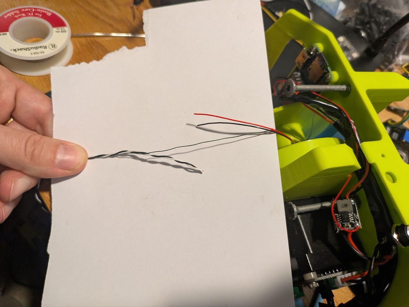
Prepare two appropriately sized heat shrink tubes. Put them onto the wires before beginning the splice. Splice both conductors. black to black, and red to gray.
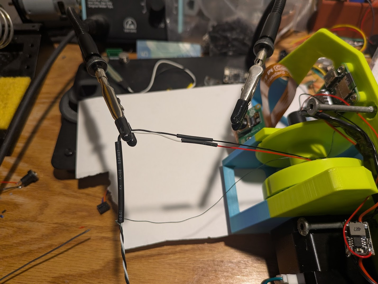
Shrink the small tubes for each conductor first, then the large heat shink tube around them both.
Warning
Keep flame or heat well away from the fishing line. If you damage it with flame, even if it appears intact, cut the splice out and start over.
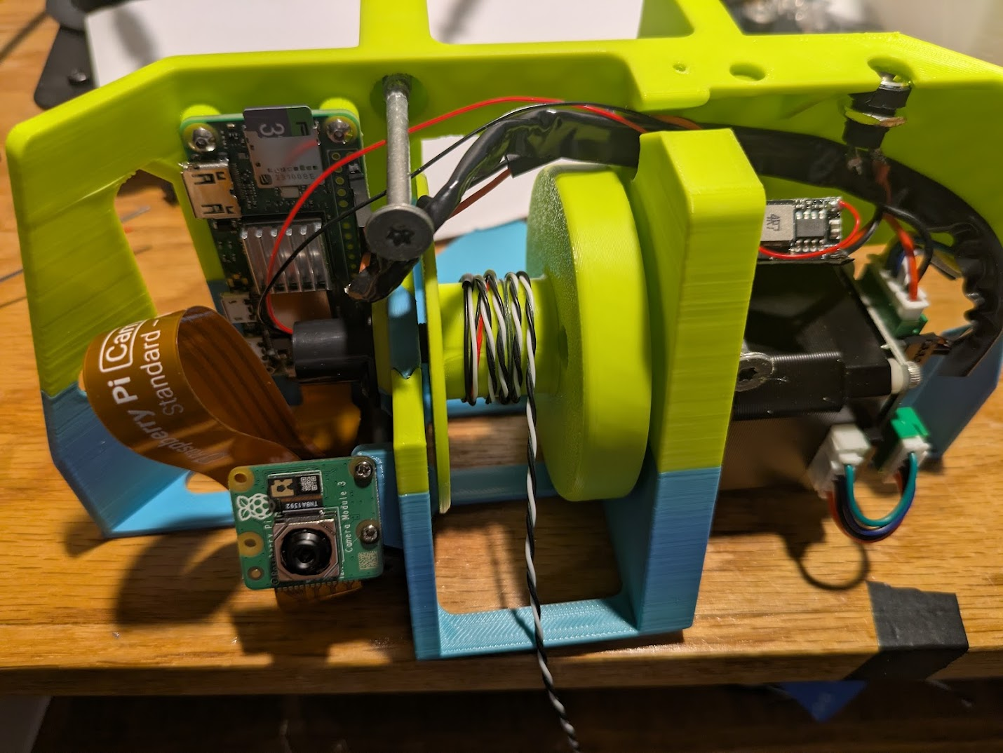
After completing the splice, manually wind a few turns of the powerline onto the spool in the pictured direction.
There is a script in qa/anchor_eval.py that automatically winds the correct length of fishing line or power line onto the spool. In order to run it you will have to Proceed with all the raspberry pi software setup now before continuing.
After installing the software, temporarily de-activate the server and run the eval script. Follow the instruction to click the microswitch and winding will begin.
from inside cranebot3-firmware
sudo systemctl stop cranebot.service
source venv/bin/activate
python qa/anchor_eval.py
Tip
If any problems are encountered by that script, check though Quality Assurance steps but in my experience it's almost always a problem with the continuity of the hand crimped connectors
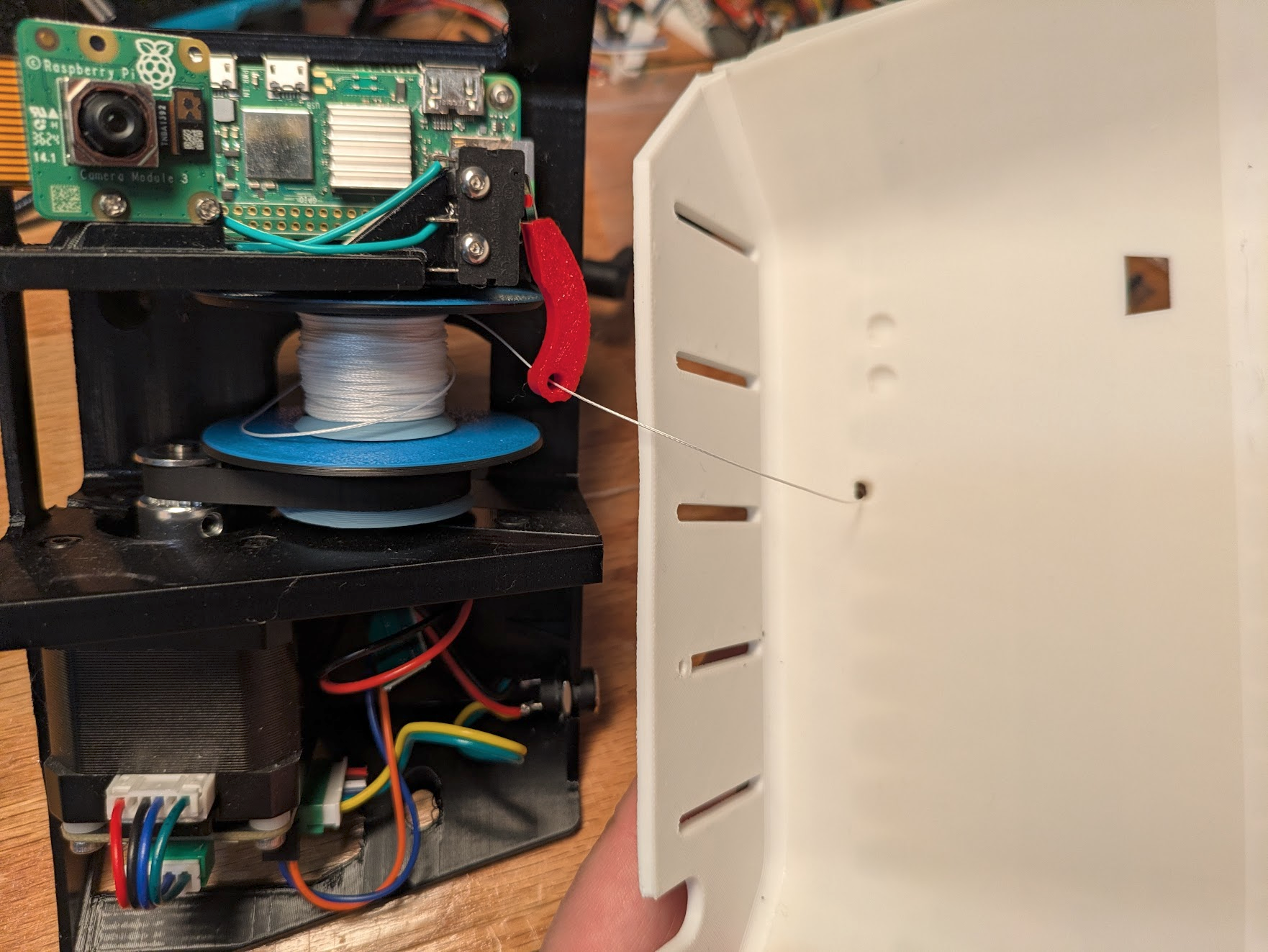
Once the correct length of fishing line or power line is wound, trim it if necessary and thread the end through the microswitch lever.
Danger
If you are trimming power line from a spool, unplug power first so your scissors don't short the two conductors.
Thread it through the hole on an appropriately shaped cover peice. Click the cover piece in place, making sure the line does not become pinched anywhere. Gently pull out about 30cm of line from the hole, confirming that the microswitch clicks when transitioning from tight to loose and back again.
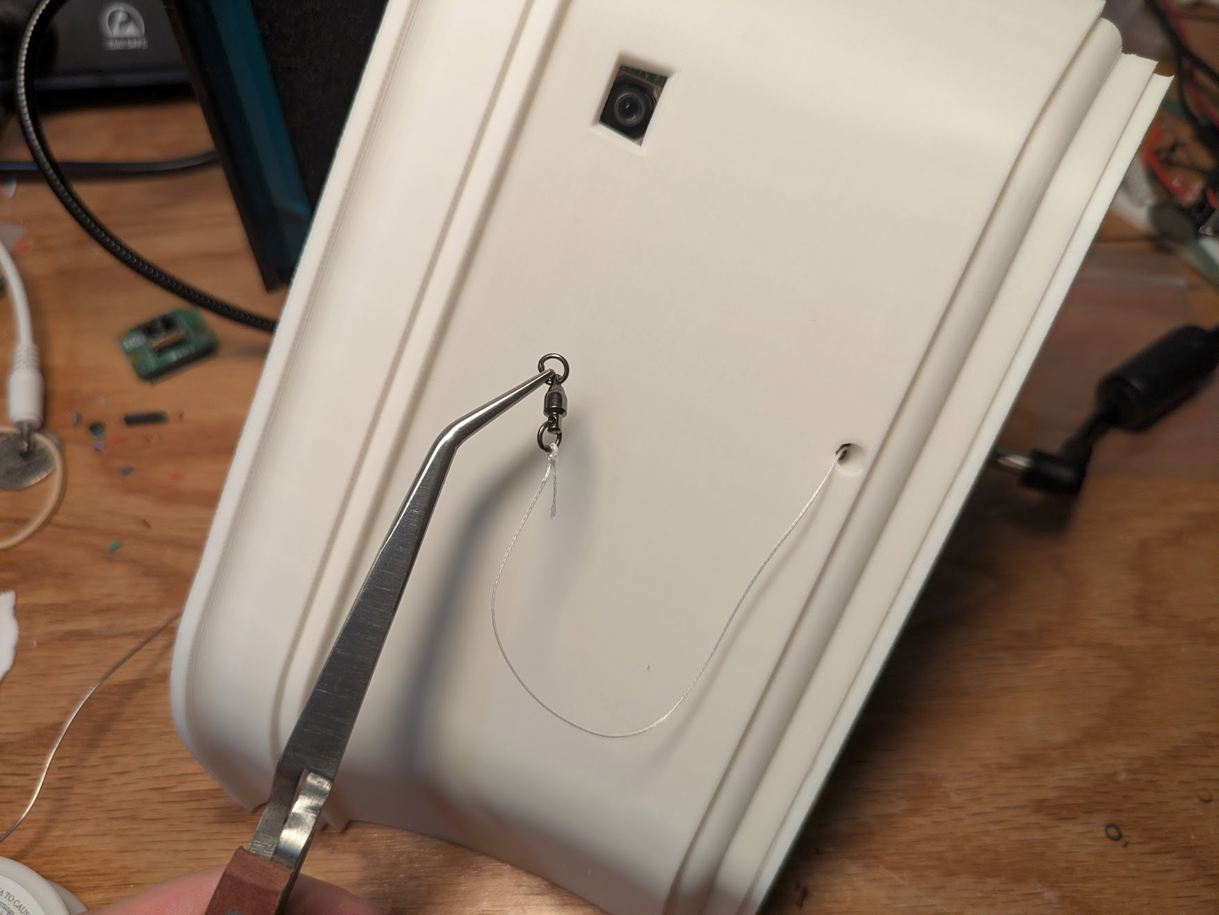
Tie a fishing swivel onto the end of the fishing line with a palomar knot.
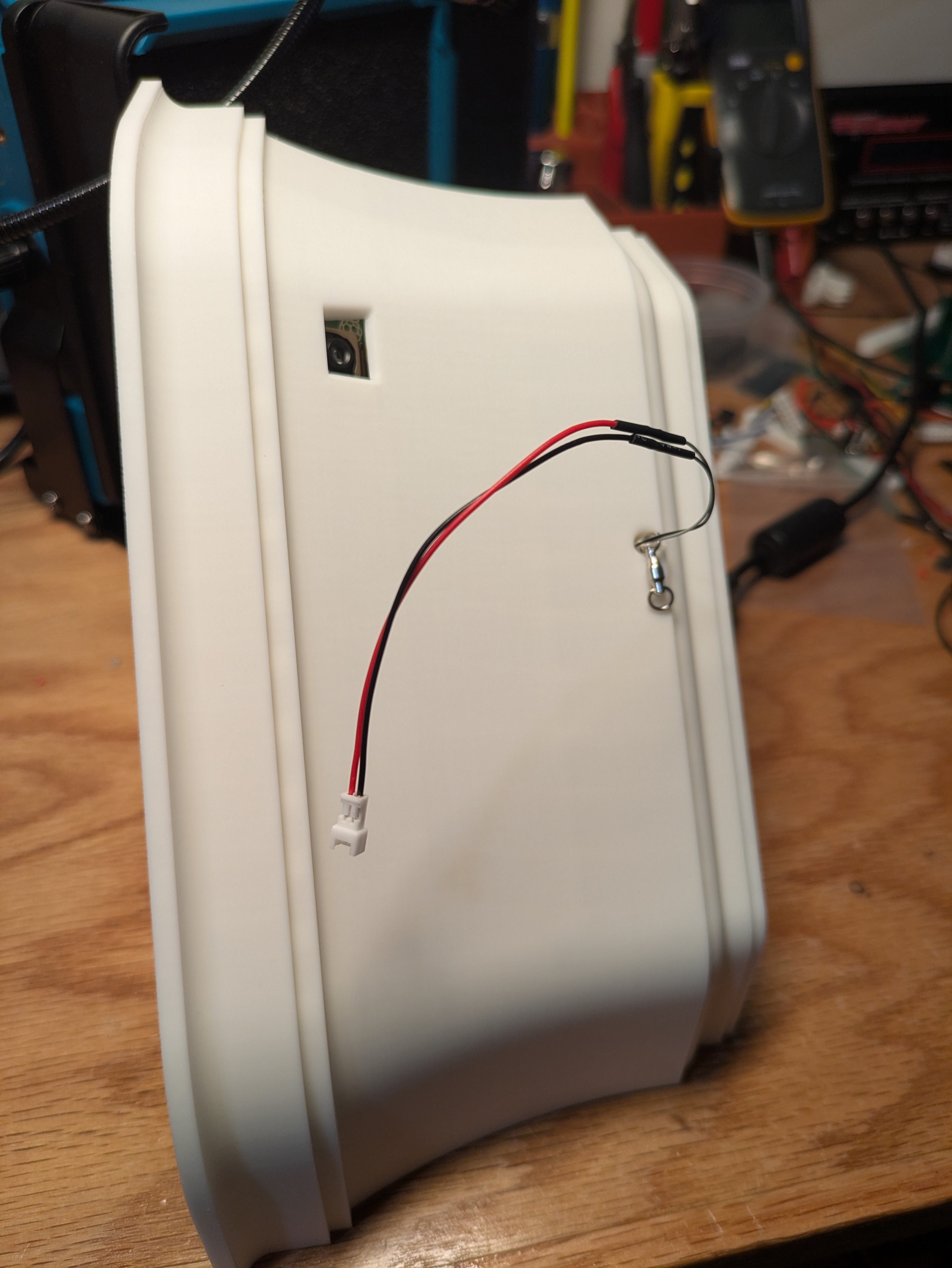
For power anchors
Splice a female JST 1.25 2P connector onto the wires with solder and heat shrink.
The anchor is complete! during installation you will temporarily remove the cover, screw it to the wall, then snap the cover back on and secure it with a single M2.5x10 screw in the bottom. You can put that screw in now as a way to not lose it.