Gantry Build Guide
Hardware Version: Pilot run
Tool list
Gantry
The gantry refers to a passive component that hangs where all the anchor lines meet and displaying markers for camera pose estimation.
Print the components of the gantry in a white or light colored filament with two walls and 12% cubic infill. Attach them together with four M3x4 screws.


Stickers
You should have received four copies of the “gantry_front” aruco marker on sticker paper. Cut out the stickers with a ruler and an exacto knife along the thin dotted line, which leaves a 1cm border around the marker. If you need to print the stickers again, You can find the document here (print 2 copies of page 2 only) and the paper on amazon


To more easily remove the backing, make a gentle cross cut into the corner of the backing with the knife with only enough pressure to cut the backing, but not the sticker. Put one sticker on each face of the gantry. They must be oriented correctly. The word “gantry_front” is printed at the bottom of each. Note that the top of the gantry is the part where the second part was screwed on. Refer to this image for the correct orientation

Thread the gripper's JST connector and fishing swivel up through the gantry's center hole. Attatch a 10mm keyring to the gripper's fishing swivel. this prevents it from falling back through the hole. This is yet another one of those situations where it's better to have cross locking tweezers for hands.
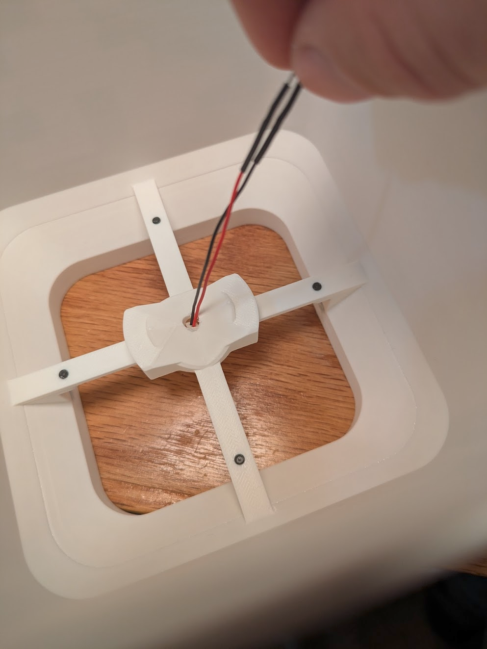


Attach four fishing speed clips to the keyring to accept the swivels from the four anchors during installation. These are just an optional time saver for ease of assembly and disassembly.


Gantry is complete. Move on to the Installation Guide when you're ready to hang it up.